 English
 Español
 русский
 中文简体
中文简体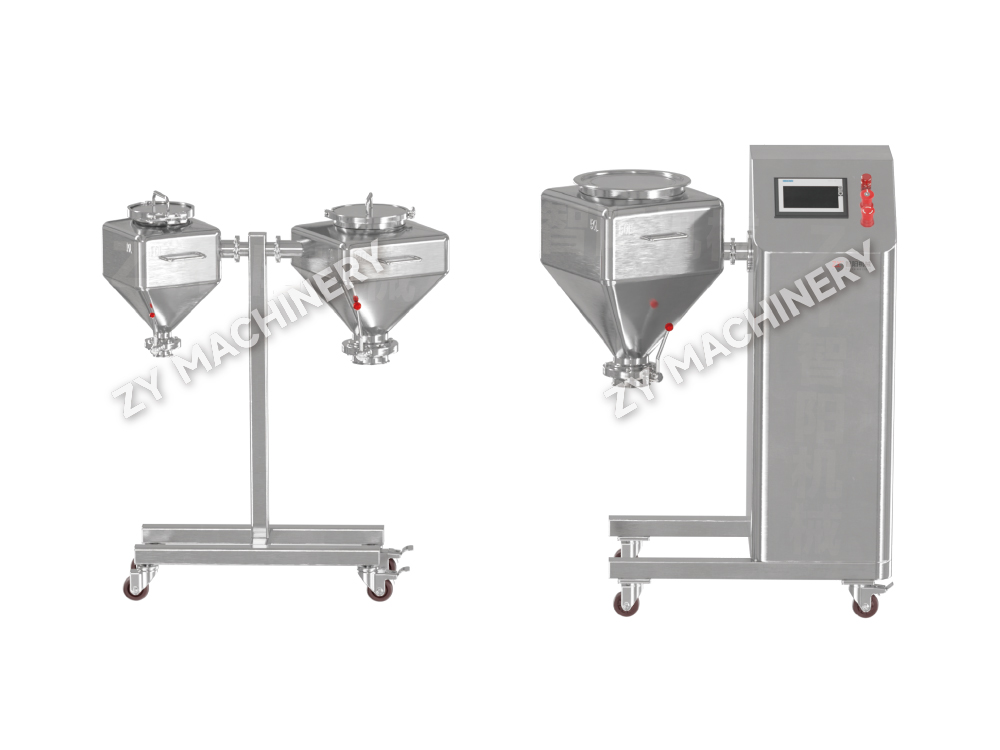
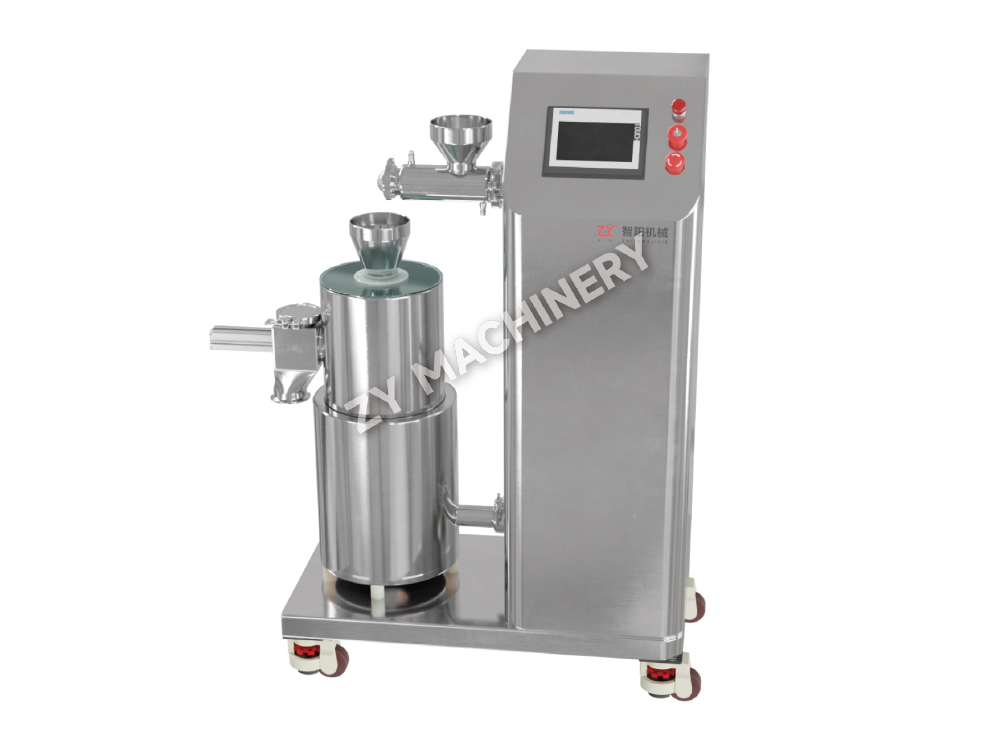
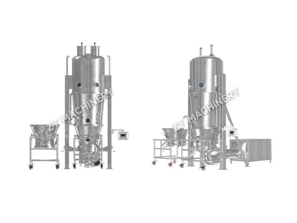
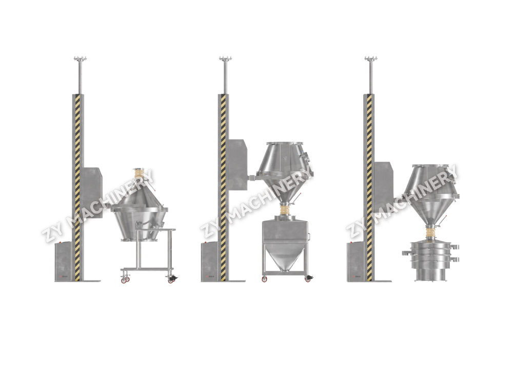
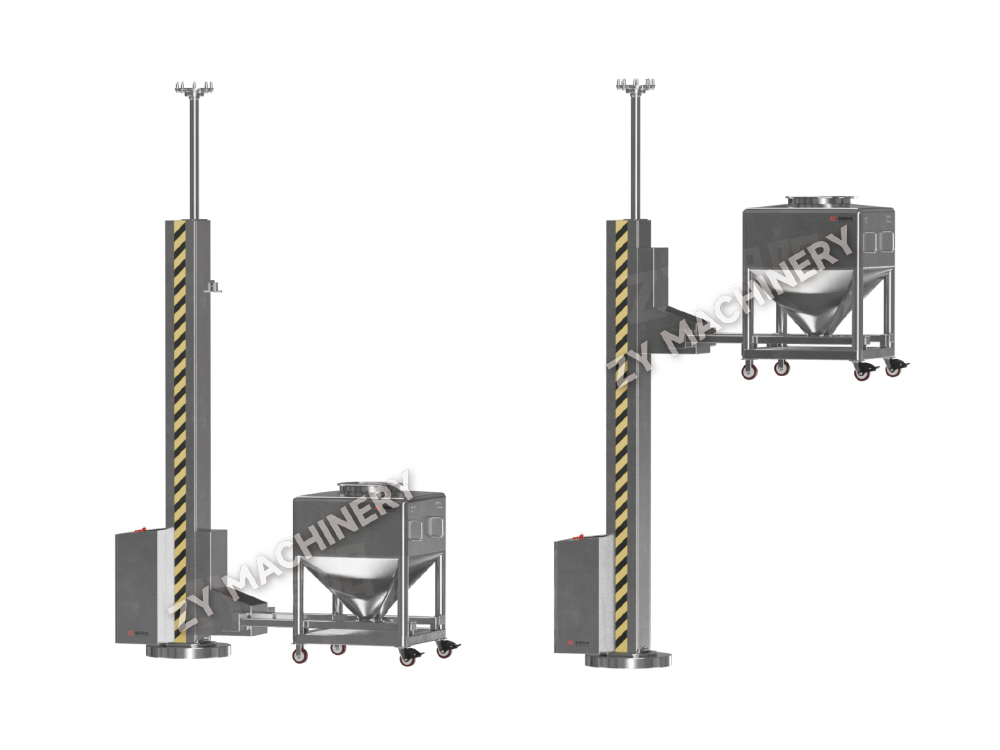
NTF Fixed Lifting and Tilting Transfer Machine
The NTF Fixed Lifting and Tilting Transfer Machine is designed for the tran.....

Content
A project team once spent eight months on a facility layout only to discover during basic engineering that the building would not support the required pressure cascades for a high-containment block. The root cause was simple: they started drawing walls before completing a formal design basis. For oral solid dosage (OSD) manufacturing, every successful plant design begins with three non-negotiable answers: the exact dosage forms and product characteristics, the intended annual output in kilograms or tablets, and the primary regulatory jurisdictions (FDA, EMA, NMPA, etc.). Without these, equipment sizing, cleanroom classification, and even corridor widths remain guesswork.
A design basis document should capture more than the blockbuster molecule name. It must define the API's occupational exposure band (OEB), its sensitivity to moisture and heat, the batch size range, and whether the process includes solvents that trigger ATEX zoning. If the plant will handle both immediate-release and modified-release tablets, the facility must accommodate separate granulation lines or at minimum validated cleaning procedures between campaigns. Multi-purpose plants add flexibility but multiply validation effort—a trade-off that needs quantification early.
| Dosage Form | Minimum Cleanroom Grade | Typical HVAC Special Condition | Key Equipment Material | Containment Risk |
|---|---|---|---|---|
| Standard OSD tablets | D | General humidity control 40–55% RH | 316L stainless steel product-contact parts | Low (OEB 1–2) |
| Effervescent tablets | D with low-humidity suite | Dew point <10 °C, sealed room | 316L, special sealing | Low to moderate |
| Dry powder inhalers | C | Stringent particle control, low humidity | Pharmaceutical-grade stainless steel | Moderate (OEB 2–3) |
| Potent OSD (hormones, cytotoxics) | D (contained) | Negative pressure cascades, single-pass air | 316L, electropolished, CIP capable | High (OEB 4–5) |
After the design basis is locked, the next step is to make material movement the organizing principle of the entire layout. This shift in thinking prevents a common mistake: designing a building and then squeezing the process inside.
In a well-designed OSD plant, the distance a powder travels between the dispensing suite and the compression machine determines not just productivity but also cross-contamination risk. Every 10-meter reduction in manual transfer distance lowers the probability of airborne dispersion of active ingredients by approximately 15% and shaves close to 8% off direct labor hours per batch. That is why the material flow diagram should be drafted before the first architectural line is drawn.
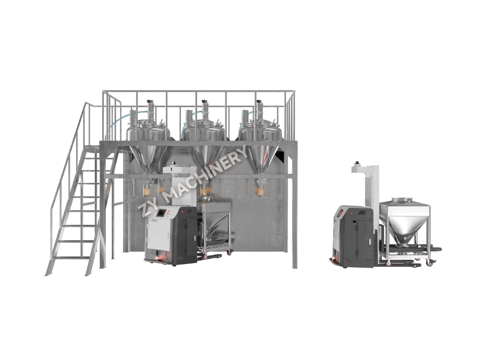
The typical flow for a tablet line—dispensing, wet or dry granulation, drying, size reduction, blending, compression, coating, and packaging—creates natural functional zones. These zones should follow a unidirectional path with no backtracking. Personnel and material airlocks isolate each zone, and tumble mixers with lift columns can eliminate the need to carry bins across corridors by transferring IBCs directly from blending to compression via gravity chutes or automated guided vehicles. This approach is not just lean; it reduces the number of pressure cascades required and simplifies HVAC zoning.
Granulation and compression suites are typically separated by a wall with a pass-through or a semi-automated transfer system. If the product is moisture-sensitive, the material backbone may also include a dry granulation roller compactor instead of a fluid bed, reducing both drying time and the risk of hydrolysis. The layout must also consider future capacity expansion. Leaving a mirrored shell space on the opposite side of a central utility spine allows doubling capacity without re-routing material flow.
Selecting granulation equipment is essentially a decision about batch size, containment, and the physical chemistry of the formulation. A molecule that degrades in the presence of water will never go through a high-shear wet granulator; it belongs in a roller compactor or a direct compression line. Yet many project schedules are delayed because the equipment list is written before the formulation’s stability profile is complete. The following matrix clarifies the decision.
| Parameter | Wet High-Shear Granulation | Fluid Bed Granulation | Dry Granulation (Roller Compactor) |
|---|---|---|---|
| CapEx (relative) | Base | +20–30% | +10–15% |
| Batch cycle time | 30–60 minutes (plus drying) | 45–90 minutes (integrated drying) | 15–30 minutes |
| Dust containment risk | Moderate (open discharge) | Low (integrated transfer) | Low (enclosed system) |
| Cleanability (CIP feasibility) | Moderate; some parts require COP | Good; many models offer WIP | Good; limited wet surfaces |
| Best for API characteristics | Stable to moisture, poor compressibility | Moisture-sensitive possible, good flow | Very moisture-sensitive or high-potency |
| Validation complexity | Medium (drying endpoint control) | Medium (process analytical technology ready) | Low (few critical process parameters) |
Beyond granulation, blending equipment must be evaluated for segregation risk. Bin blenders with lift systems are preferred over fixed V-blenders because they minimize transfer steps and are easier to validate for content uniformity. In facilities targeting OEB 4/5 compounds, the entire blending, compression, and coating train must run inside isolators or under negative pressure enclosures. This shifts the equipment selection calculus toward compact, fully integrated systems with validated containment interfaces.
When the active pharmaceutical ingredient carries an occupational exposure limit below 1 µg/m³ (OEB 4 or 5), the facility design moves from product protection to operator protection as the dominant logic. The isolation strategy becomes the architectural backbone: each process step is sealed, and the room around it is maintained at a negative pressure relative to adjacent corridors, typically with a target pressure differential of at least 15 Pa and a dedicated once-through air handling system that does not recirculate to general areas.
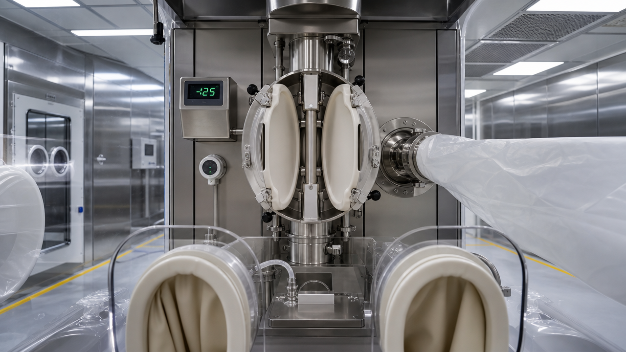
A validated split butterfly valve (SBV) must achieve a leakage rate of less than 1 µg/m³ during material transfer between an IBC and a tablet press inlet. The isolator’s HEPA filtration must be rated H14 with a documented DOP test pass. Below is the minimum checklist for OEB 4/5 equipment packages:
The classification of the surrounding room is still typically Grade D (ISO 8) at rest, but the pressure cascade imposes a flow of air from the general corridor (atmospheric) into the potent compound airlock (minus 7.5 Pa) and then into the process room (minus 15 Pa or more), creating a continuous inward sweep that protects the operator. Modern designs often add an anteroom with a HEPA-filtered air shower to contain any particle escape during material movement.
Heating, ventilation, and air conditioning account for 40–60% of a pharmaceutical plant’s operating expenditures. Getting the pressure cascade wrong leads to either regulatory observations or excessive energy bills. The EU GMP Annex 1 and FDA aseptic guidance drive the required environmental parameters. For OSD facilities, the target is maintaining Grade D conditions in occupied processing rooms, but with more stringent humidity control for effervescent or moisture-sensitive products. The table below summarizes the critical HVAC setpoints.
| Grade | ISO Class (at rest) | Air Changes per Hour | Pressure Differential vs Adjacent Lower Grade | Particulate Limits (≥0.5 µm, at rest) | Viable Limits (cfu/m³, operative) |
|---|---|---|---|---|---|
| A (for sterile) | 5 | Not defined (velocity 0.45 m/s) | Not applicable | 3,520 | <1 |
| B | 5–7 | 40–60 | 15 Pa to C | 3,520 | 10 |
| C | 7–8 | 20–40 | 12.5 Pa to D | 352,000 | 100 |
| D (OSD standard) | 8 | 15–20 | 12.5 Pa to unclassified | 3,520,000 | 200 |
The 12.5 Pa minimum is not a suggestion; it is a design setpoint that must be maintained during door openings and equipment operation. Active monitoring and building management system alarms should trigger when the differential drops below 10 Pa. For OSD plants, a common failure point is the dust extraction system, which must be interlocked with the HVAC supply to avoid negative imbalances. When a fluid bed dryer is in blow-and-extract mode, the room’s pressure control must compensate for the large exhaust volume.
Validation is not a post-installation activity; it begins the moment a user requirement specification is drafted. A well-structured URS that defines material of construction, surface finish (Ra ≤ 0.4 µm for product-contact surfaces), drainability, and cleaning method pre-empts 70% of the deviations later found during IQ/OQ. In a typical project timeline, executing a thorough Factory Acceptance Test reduces site commissioning effort by up to 30% because most mechanical and software bugs are resolved before the equipment leaves the vendor’s shop.
For multi-product facilities, the validation master plan must include a bracketing strategy that groups products by solubility and potency to minimize the number of cleaning validation runs. Riboflavin testing and swab recovery studies provide the baseline for the final cleaning acceptance criteria.
A greenfield plant built using pre-validated modular process skids can be mechanically complete 3–6 months faster than a stick-built equivalent, but the upfront engineering cost is typically 10–15% higher because of the intensive front-end design required to freeze piping and instrument locations. However, that premium is often recovered by earlier market entry: launching a generic product four months earlier can capture 8–12% additional market share before competitors erode pricing. The comparison below uses a hypothetical 2-billion-tablet-per-year OSD facility.
| Parameter | Modular/Skid-Based | Traditional Site-Built |
|---|---|---|
| Total project duration (design to PQ) | 22–28 months | 28–36 months |
| Capital expenditure (relative) | +10–15% | Base |
| Validation effort | 20–30% lower (pre-validated modules) | Full site validation from scratch |
| Future scalability | Flexible; add parallel skids | Requires structural modifications |
| Construction quality variability | Low (factory-controlled) | Higher (site-dependent) |
| Typical cleanroom footprint | 15–20% smaller (optimized piping) | Larger due to on-site routing |
Beyond time and cost, the modular approach simplifies technology transfer because the same skid design can be replicated across multiple geographies with minimal re-validation. However, if the product portfolio is expected to change significantly within five years, a traditional building with wider column spacing and generic utility drops may offer more reconfiguration freedom. The final choice comes down to the certainty of the product pipeline.
The next generation of OSD plants will not rely on periodic sampling for quality release. Process Analytical Technology sensors—NIR probes mounted in blenders and dryers, particle size analyzers on granulator discharges—enable real-time monitoring of critical quality attributes. When integrated with a Manufacturing Execution System via OPC UA data highways, these signals can provide the justification for real-time release, eliminating days of quarantine storage. A digital-ready plant requires the following integration points designed from day one:
Regulators expect that electronic records replace paper logbooks, but they also expect that the system is validated to detect data manipulation. Including PAT and digital integration in the initial V-model validation plan costs approximately 12% of the total project controls budget, but it reduces the ongoing cost of quality oversight by an estimated 20% annually through reduced laboratory testing and batch record review hours. Plants designed without digital readiness find themselves retrofitting during the first expansion, at three times the original cost.
Want to stay up to date?
Contact us via the email address below.
Don't worry about spam. We hate it too!
Mobile Client
Video Account
Phone:+86-15161130178
Tel:+86-519-88674267
Email:czzy188@163.com
Phone:+86-15161132798
Email:zy@zy-drying.com

WeChat ID

Copyright 2026 Changzhou Zhiyang Machinery Equipment Co., Ltd. All Rights Reserved  Oral Solid Dosage Equipment Manufacturer