 English
 Español
 русский
 中文简体
中文简体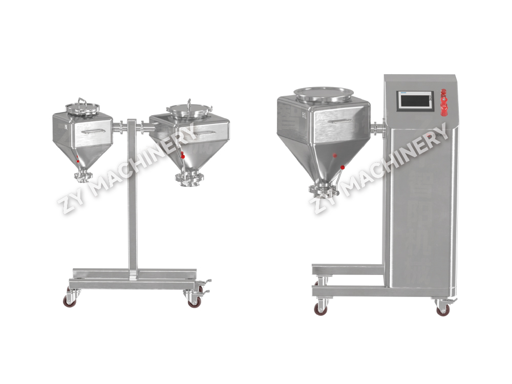
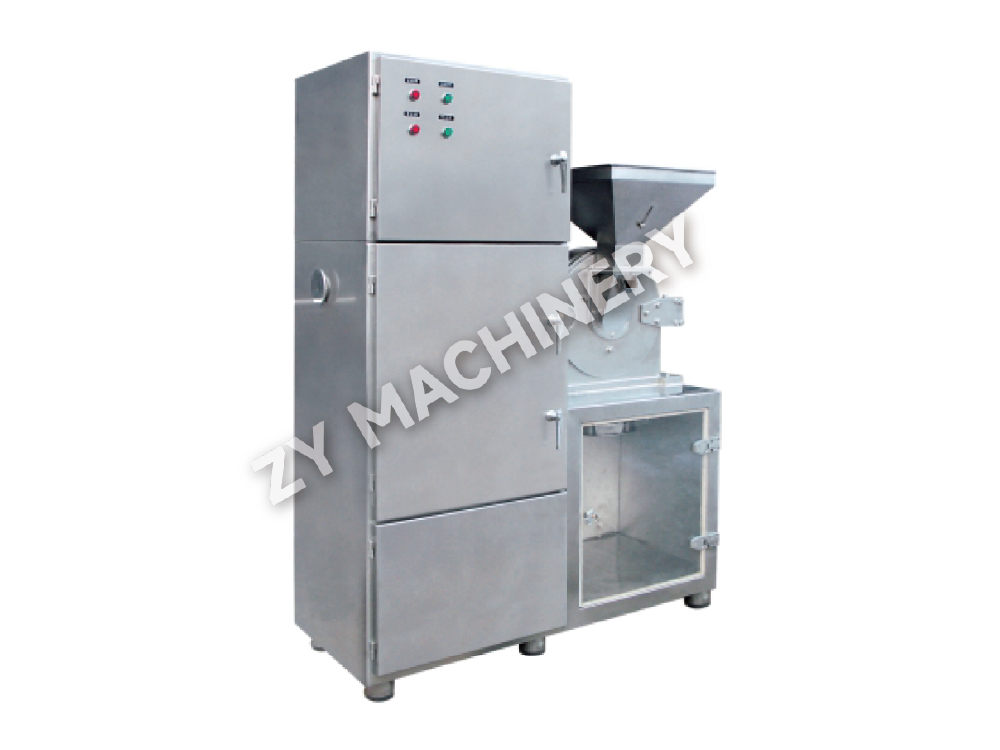
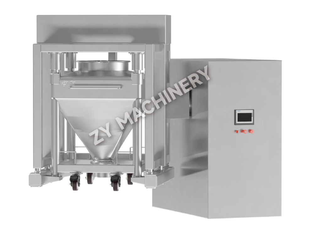
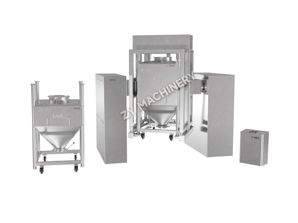
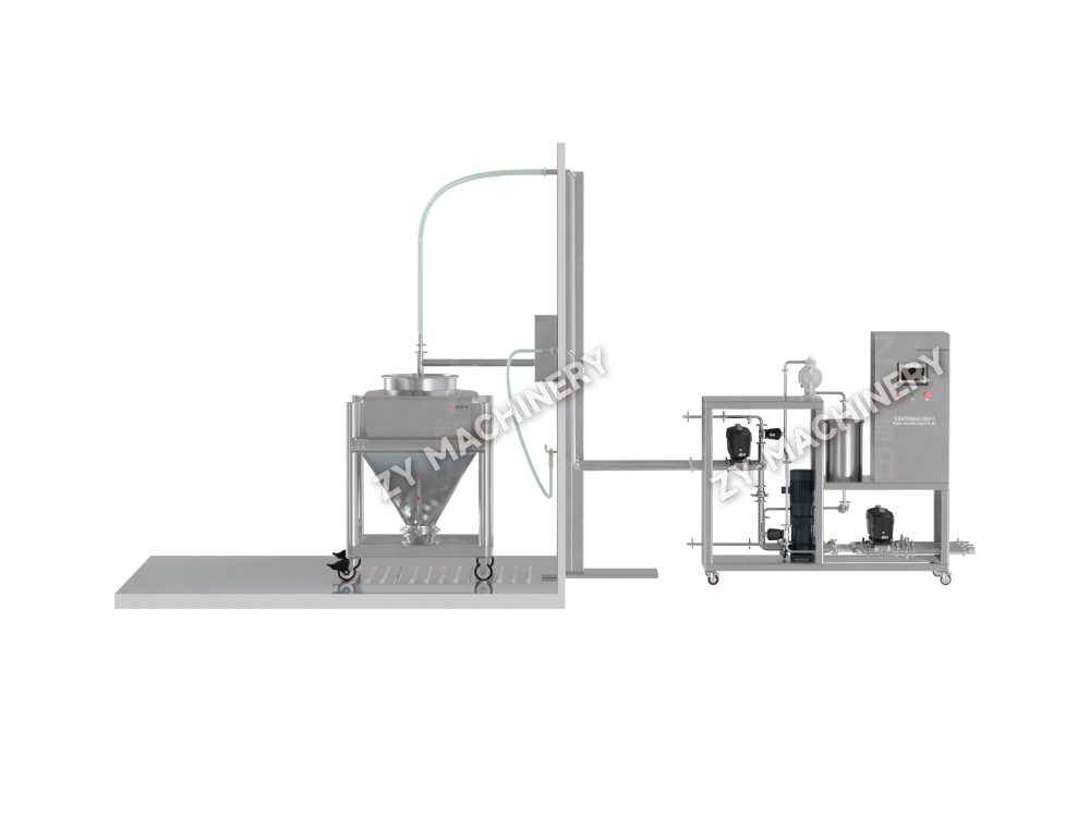
AH Airflow Mixer
The AH Airflow Mixer is specifically designed to meet the batch mixing requ.....

Content
A single capping defect can trigger a full batch rejection, costing $50,000 or more in wasted materials and lost production time. Tablet defects are rarely isolated—they usually signal an interaction between formulation design, equipment setup, and process parameters. Treating each defect as a standalone problem leads to repetitive troubleshooting. Instead, the most successful organizations map defects back to three interconnected root categories: formulation (the composition and physical properties of the granulate), equipment (press condition, tooling geometry, cleaning residues), and process (compression force profile, speed, pre‑compression dwell).
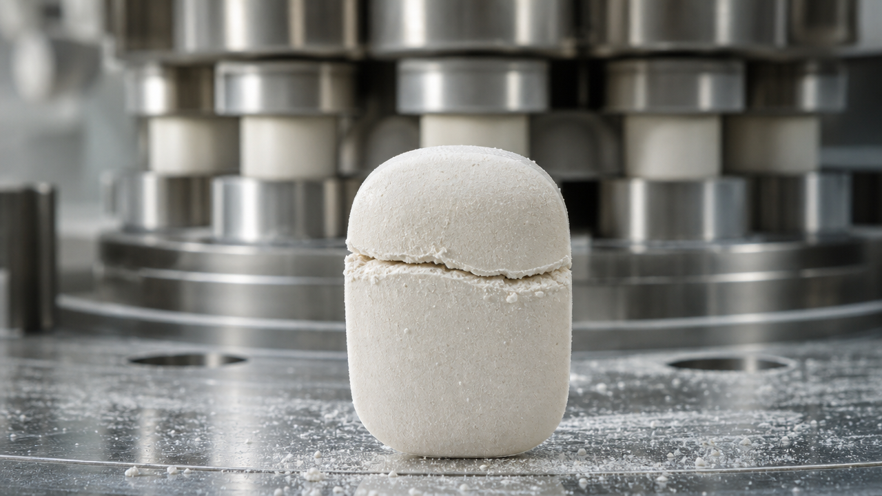
For instance, capping and lamination often trace back to excess fines in the granulate, but those fines may result from an overly aggressive dry‑granulation step or from a drying profile that leaves the surface brittle. Sticking, on the other hand, might originate from a lubricant deficiency, but the real trigger could be a fluctuation in clean‑in‑place (CIP) residues that modifies punch face friction. The best pharmaceutical engineers build a defect‑diagnosis matrix that connects formulation variables like moisture content (optimal range 1.5–3.0% for most immediate‑release formulations), lubricant type and concentration, and API particle size to the specific defect observed. Below 1.5% moisture, capping risk increases dramatically because the granules lack the plasticity to form strong interparticular bonds. Above 5%, sticking becomes nearly inevitable without preheating or dehumidified compression suites.
This article moves from general principles to specific defect categories, then to the role of granulation method, scale‑up, and advanced monitoring. Every recommendation is grounded in measurable thresholds and equipment‑specific adjustments, so you can move from diagnosis to correction in a single shift.
Capping is the horizontal separation of the tablet top (or bottom) from the main body; lamination is a similar fracture that can appear anywhere along the horizontal axis. Both defects indicate weak bonding between layers formed during compression. The primary drivers fall into four buckets: too many fines in the granulate, excessive lubricant, insufficient binder, and incorrect compression settings. The mixing equipment used to blend lubricants sets the stage: if magnesium stearate coats particles too heavily because of overmixing or wrong shear conditions, even a 0.5% increase above the nominal 1.0% w/w can drop tablet hardness by 30–40%. Pre‑blending the lubricant with a small portion of fines before adding to the main mass can reduce this over‑coating effect without reducing total lubricant.
In terms of compression, a pre‑compression force below 5 kN often fails to expel enough air from the die before main compression. The trapped air then expands after ejection, causing a cap. A pre‑compression setting of 8–12 kN, combined with a main compression force of 15–25 kN (for a typical 200‑mg tablet of hardness 7–10 kp), dramatically reduces capping. Press speed also matters: at speeds above 60 rpm on a rotary press, contact time between punch and granulate drops, which can lead to incomplete bond formation. Reducing speed to 30–45 rpm while maintaining pre‑compression often solves the problem without reformulation.
| Cause | Symptom | Corrective Action (with threshold) |
|---|---|---|
| Excess fines (>25% below 75 μm) | Lamination at low hardness | Increase granule density via wet massing time or use fluidized‑bed drying to retain fines in agglomerates |
| Low moisture (<1.5% w/w) | Brittle capping on ejection | Adjust drying endpoint to 2.0–2.5% LOD; consider post‑drying conditioning in sealed bins |
| Excessive lubricant (>2% MgSt) | Weak capping with shiny fracture | Reduce MgSt to 0.75–1.0%; change blending sequence; switch to sodium stearyl fumarate if hydrophobic effect persists |
| Insufficient pre‑compression | Air entrapment capping at high speed | Set pre‑compression to 30% of main force; verify dwell time >50 ms |
A common misconception is that increasing main compression force alone can fix capping. In reality, overcompression (above 30 kN for a standard concave punch) can induce elastic recovery stresses that make capping worse. A better approach is to build a compaction profile: compress a sample of granulate at increasing forces and measure the resulting tablet’s capping tendency at each force; the “sweet spot” is the lowest force that achieves target hardness without introducing lamination.
Sticking occurs when granulate adheres to the punch face, leaving a rough, pitted tablet surface; picking is a more localized form where material fills the embossing or debossing recesses. The two most common triggers are moisture content above 3.5% and insufficient lubrication. But there is a less obvious third factor: microscopic roughness on punch faces caused by repeated cleaning cycles. When a punch is cleaned with abrasive media or aggressive chemicals, its surface finish degrades, and even a properly lubricated granulate can start sticking. Facilities that run multiple product changeovers per day often see a spike in sticking complaints traceable to punch wear, not formulation drift.
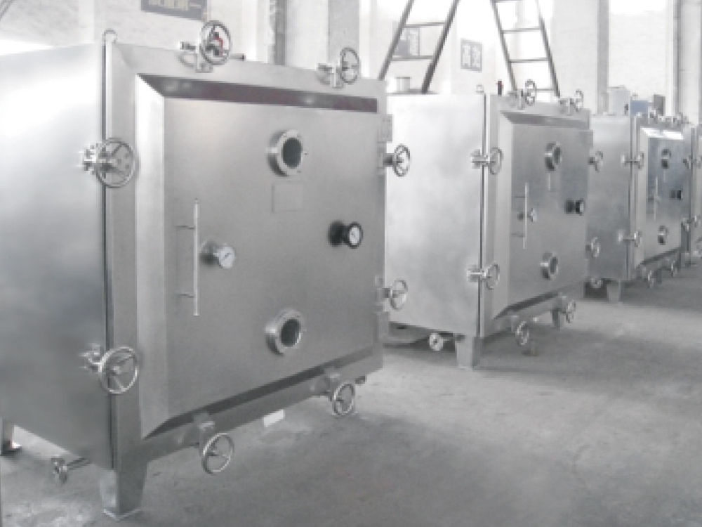
From a process standpoint, the drying step is your first lever. In vacuum drying, moisture can vary by 0.5% between the top and bottom of the tray if the vacuum ramp rate is too fast. A slow ramp (10–15 minutes to full vacuum) evens out the gradient. For wet granulation, target an LOD of 2.0–3.0% unless the formulation is hygroscopic; in that case, consider a post‑drying blending step with 0.5% colloidal silica to scavenge surface moisture.
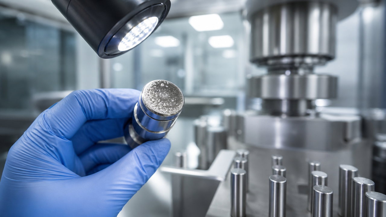
Lubricant choice and amount are equally critical. For sticking, the effective lubrication concentration can be much lower than what the formula card says if the blender design leaves dead zones. A V‑blender or bin blender with intensifier bar used at 200–300 RPM for 3–5 minutes achieves better coverage than a simple tumble without intensification. The V‑type mixer is particularly effective for low‑dose APIs where lubricant distribution must be flawless. For formulations where MgSt causes dissolution slowdown, PEG 6000 at 1–2% often eliminates sticking while keeping disintegration within USP limits.
A quick checklist when sticking appears:
Chipping refers to small pieces breaking away from the tablet edge, often after coating or packaging. It is strongly correlated with low tablet edge hardness and poor film coating adhesion. Tablets with a breaking force below 5 kp and high friability (>0.8% in a standard friabilator) are prime candidates. Cracking appears as fissures on the tablet surface or within the coating, while flaking is the separation of the coating layer from the core.
To prevent chipping, the core must have sufficient mechanical strength at the rim. A granulation process that yields a narrow particle size distribution with low fines minimizes die‑filling inconsistencies that create weak edges. The tooling design also matters: a deep concave punch profile concentrates stress at the thin edge; switching to a shallow concave or bevel‑edge design can increase edge integrity by 25% or more in commercial runs. For film‑coated tablets, the coating pan speed must be adjusted so tablets do not cascade too aggressively during the spray phase, because edge collisions at high velocity initiate micro‑cracks that later become visible chips.
Coating polymer selection directly influences cracking and flaking. A comparison of common polymers is shown below.
| Polymer | Key property | Typical defect risk | Recommended adjustment |
|---|---|---|---|
| HPMC (hydroxypropyl methylcellulose) | Good adhesion, low oxygen permeability | Cracking under high humidity cycling | Add 10–15% PEG 400 as plasticizer |
| PVA (polyvinyl alcohol) | Excellent flexibility, glossy finish | Sticking in pan at high spray rate | Increase inlet air temperature by 5 °C |
| Ethylcellulose (EC) | Controlled release, brittle film | Flaking if plasticizer <20% | Use triethyl citrate at 20–25% |
When cracking appears shortly after coating, a common root cause is residual moisture from the coating process migrating into the core and causing dimensional change. Preheating the tablet bed to 40–45 °C for 10 minutes before spraying, and maintaining a product temperature of 38–42 °C during coating, reduces this effect.
The granulation technique imprints a defect “fingerprint” on every batch. Wet granulation produces granules with higher internal porosity and more rounded shapes, which generally compact well but are moisture‑sensitive. Dry granulation (roller compaction) creates ribbons that mill into irregular, dense fragments rich in fines; these granules are brittle and often cause lamination unless a careful rebonding step is used. Fluid‑bed granulation yields low‑density, highly spherical agglomerates with excellent flow but occasionally weak interparticulate bonding because the low bulk density reduces contact points under compression.
The table below summarizes the defect susceptibility of each method.
| Granulation method | Particle morphology | High‑risk defects | Mitigation approach |
|---|---|---|---|
| Wet high‑shear | Dense, rounded, wide particle size distribution | Sticking if over‑wetted; capping if under‑dried | Control LOD to 2.5% ± 0.3% |
| Fluid‑bed | Low‑density, highly spherical, uniform | Lamination at high speed; low hardness | Increase main compression force by 15% |
| Dry (roller compaction) | Irregular, angulated, high fines fraction | Lamination, capping, weight variation | Use a second blending step after milling; add 1–2% dry binder like PVP |
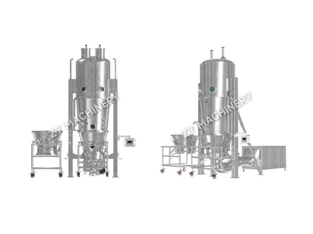
Choosing the right granulation equipment can pre‑empt these defects. When a formulation is sensitive to heat and moisture, dry granulation via roller compaction is the logical choice, but the equipment must include a multi‑sieve milling system that recycles only a controlled portion of fines back to the compaction stage. Conversely, for formulations where compactibility is paramount, a high‑shear wet granulator followed by fluid‑bed drying creates granules with the ideal balance of strength and compressibility. The ability to adjust impeller speed and wet massing time is essential for tuning the granule porosity that prevents lamination.
The defects you eliminate in lab‑scale development often reappear during scale‑up, and for a predictable reason: compression contact time, die fill consistency, and environmental exposure change as the equipment grows. A lab press running at 8,000 tablets per hour with a 10‑mm flat‑faced punch has almost three times the dwell time of a production press running at 100,000 tablets per hour with the same tooling. This reduction in dwell time directly increases the risk of capping and weight variation.
To maintain defect‑free performance across scales, follow this five‑step verification protocol:
Environmental control also becomes critical at scale. A 50‑kg bin of granulate stored in an unconditioned corridor can pick up 0.5% moisture overnight, enough to push a borderline formulation into sticking territory. Sealed containers and a short holding time (under 8 hours) between granulation and compression are indispensable.
Reactive troubleshooting is giving way to in‑line process analytical technology (PAT). Near‑infrared (NIR) probes mounted on the press can detect tablet density variations every 20‑30 ms, identifying a developing capping trend long before a visual defect appears. Raman spectroscopy, integrated into the ejection chute, verifies polymorphic form and can detect subtle changes in API crystallinity that precede sticking. In one published case, a manufacturer reduced capping‑related rejects by 62% after installing an NIR system that provided real‑time feedback to adjust pre‑compression force automatically.
Equipment‑side improvements are equally transformative. Highly potent or cytotoxic formulations processed in containment systems face unique defect risks: static charge accumulation inside isolators pulls fine particles away from the die, causing weight variability; humidity fluctuations within sealed containment can create sticky granulate conditions that go unnoticed until defects appear. Modern isolator designs incorporate active humidity control and ionizing bars that neutralize static, minimizing these issues.
CIP (clean‑in‑place) systems for bins and presses now play a direct role in defect prevention. Inconsistent manual washing leaves trace surfactants or metal residues; a single poorly rinsed bin can cause sticking on an entire batch by altering punch surface energy. Automated auxiliary cleaning equipment delivers a validated, repeatable cleaning cycle with final rinse conductivity monitoring, ensuring no residue migrates to the next batch. This is particularly important for contract manufacturers that switch between products frequently.
Eliminating tablet defects is not about finding a single “fix” – it is about building a system that correlates formulation, equipment, and process data into a predictive model. When a new capping trend appears, the engineer who can trace it back to a 0.2% change in lubricant uniformity or a 5‑rpm press speed drift is the one who resolves it in hours, not weeks. The most resilient operations standardize defect‑response protocols around quantified thresholds, invest in granulation equipment that delivers consistent particle properties, and leverage real‑time monitoring to turn defects from surprises into controllable process signals. With the tools and frameworks outlined here, that level of control is entirely within reach.
Want to stay up to date?
Contact us via the email address below.
Don't worry about spam. We hate it too!
Mobile Client

Video Account
Phone:+86-15161130178
Tel:+86-519-88674267
Email:czzy188@163.com
Phone:+86-15161132798
Email:zy@zy-drying.com

WeChat ID

Copyright 2026 Changzhou Zhiyang Machinery Equipment Co., Ltd. All Rights Reserved  Oral Solid Dosage Equipment Manufacturer