 English
 Español
 русский
 中文简体
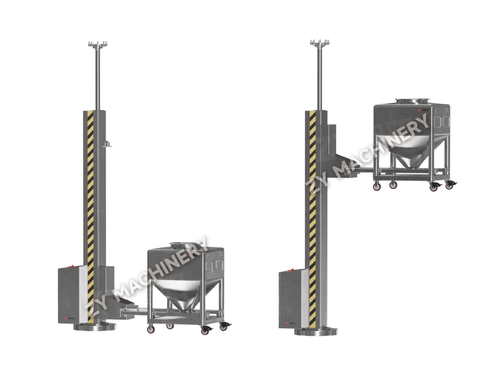
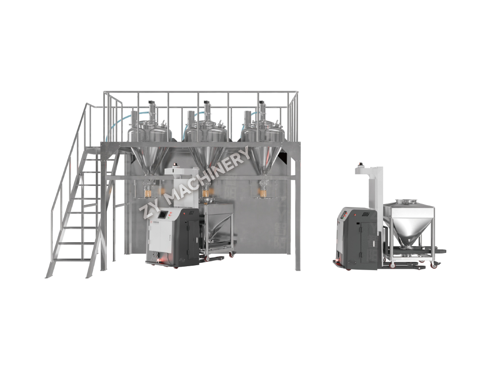
NTD Bin Lifting and Feeding Machine
The NTD Bin Lifting and Feeding Machine is used for conveying and feeding s.....

Content
Every layout discussion in our office tends to start the same way. Someone unrolls a floor plan, and the first question is rarely about the drawing itself — it is about the recipe. A layout is only as good as the process it is built around, and in oral solid dosage production that usually means working backwards from the tablet, the capsule or the granule to the rooms that have to support it. What follows is a collection of the practical points we keep returning to when planning a pharmaceutical plant layout design, from the four flows that decide circulation to the ceiling height you will wish you had specified earlier.
A sound pharmaceutical plant layout design begins with a short list: which unit operations the product needs, in what order, and at what batch size. Wet granulation followed by fluid bed drying asks for a very different building than direct compression with a dry granulation step inserted upstream. Before any wall is drawn, we usually work through three questions with the client's process team:
The answers decide the shape of the building far more than any standard template. It is also worth being honest about cost. Once the concept is fixed and the room heights are set, most of the facility's lifetime cost is already committed — the air handling tonnage, the cleanroom panels, the lift shafts. Changing a granulation room from four metres to six metres of clear height after the steel is up is not a design revision; it is a new project.
Most of the circulation problems we are asked to solve come down to four flows competing for the same square metres. Getting them onto paper early, as separate coloured lines, exposes conflicts long before they become corridors nobody can use.
People are the most mobile and least predictable element in the building. Operators should move from less clean to cleaner areas in a single direction, entering through change rooms at the clean end and leaving without crossing the raw material route. Gowning rooms sized for the shift, not for the drawing, and a control room placed so that one supervisor can see the granulation and compression areas without walking through either, save more time over a decade than most equipment upgrades.
Components enter, bins move, finished product leaves — and no route should double back. In solid dosage plants, the intermediate product spends most of its life in a bin or a container, so bin routes deserve to be drawn as carefully as pipework. Lifting height, transfer points and buffer positions all belong in the concept, not in the detail design. Our own experience with material flow and GMP compliance in plant design keeps confirming the same thing: the shortest bin route is usually the one that was planned first.
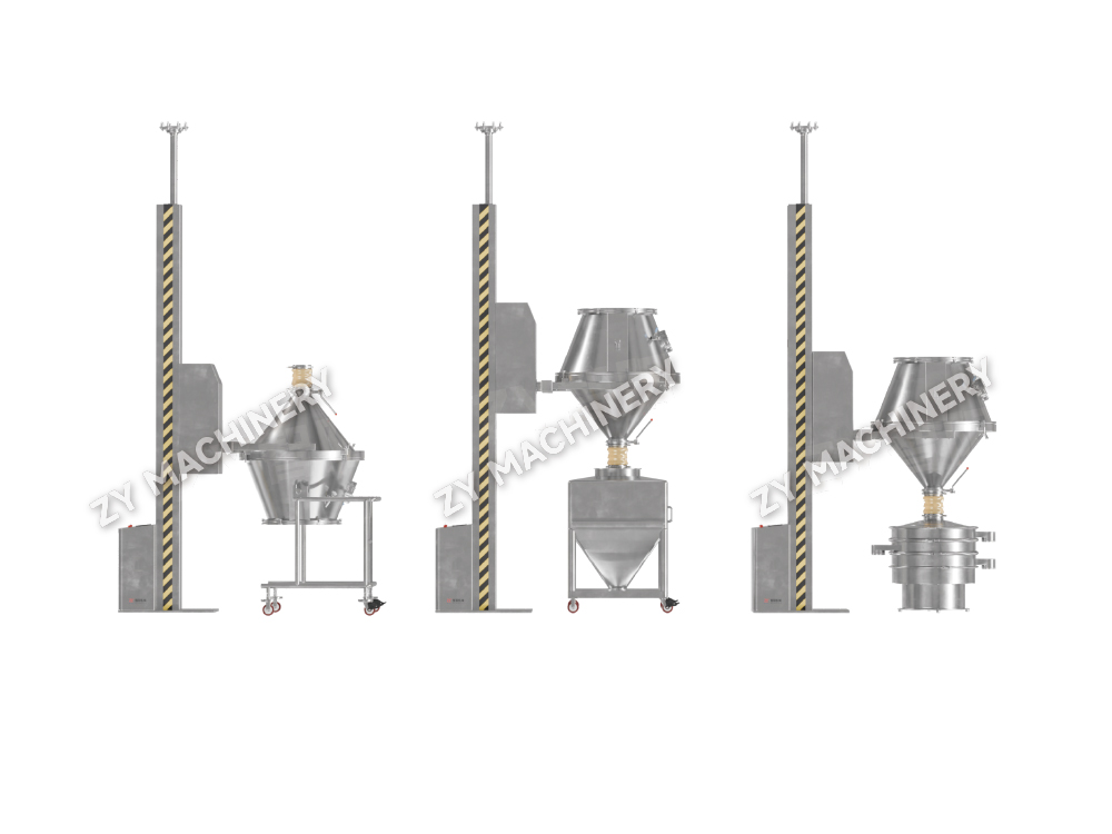
 HZD Automatic Lifting Bin Mixer for Integrated Bin HandlingSupports automatic lifting, clamping, mixing and lowering in one bin, helping shorten repeated transfer steps and plan cleaner material routes.View Product →
The sequence of unit operations sets the spine of the building. Grouping by process step suits single-product lines with high volume; grouping by equipment type suits multi-product sites where changeover is frequent. Whichever pattern you choose, leave the space between process steps generously — that gap is where the next product generation will be fitted.
Dust, rejected tablets, solvent vapours and cleaning water all need somewhere to go, and that somewhere should never be the main production corridor. A dedicated dirty exit, a bin washing room and a cleaning-in-place station positioned between the granulation and coating suites reduce walking, reduce contamination risk and make cleaning validation far easier to defend.
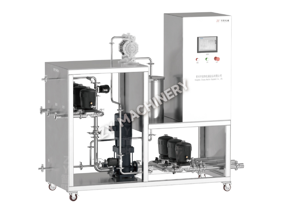 QWQY Mobile CIP Cleaning Station for Solid Dosage EquipmentProvides automated in-place cleaning for granulation, fluid-bed and coating equipment, supporting dedicated cleaning areas and easier GMP cleaning validation.View Product →
Zoning is where layout meets compliance. Grade A, B, C and D areas need to sit in a logical cascade, with airlocks and pressure differentials of roughly 10 to 15 Pa between adjacent zones so that air always moves from cleaner to less clean. The practical consequence for the layout is that rooms of the same grade should be clustered, because one air handling unit serving one grade is cheaper to run and far easier to validate than four units serving four scattered rooms.
The space people forget is the space above the ceiling and behind the wall. Air handling plant, ductwork, filter banks and service corridors regularly consume a third of the building volume, and retrofitting them into a layout that assumed a two-metre ceiling void is one of the most expensive mistakes we see. Decide early whether air handling sits on the roof, in a technical floor or in a side plant room — each choice changes the building footprint.
Equipment footprints in a catalogue are rarely the footprint you build around. Add clearance for operation, maintenance access, discharge containers, dust extraction connections and the space a technician needs to kneel beside a motor. The table below is the rough sequence we use when blocking out an oral solid dosage facility; the relationships between areas matter more than the dimensions themselves.
| Area | Typical activities | Layout considerations |
|---|---|---|
| Dispensing and weighing | Material intake, sampling, weighing | Adjacent to the warehouse; never routed through granulation |
| Granulation and drying | Wet or dry granulation, fluid bed drying | Vertical stacking where height allows; keep wet and dry zones apart |
| Blending and lubrication | Final blend, lubrication, bin handling | Short, repeatable bin routes; confirm lifting height at concept stage |
| Compression | Tablet presses, dedusting, metal detection | Floor loading, vibration isolation and separate dust extraction |
| Coating | Film or functional coating | Solvent handling and exhaust load often dominate the HVAC budget |
| Packaging | Blister, bottle, cartoning | Separate from core production; suitable for visitor access |
One equipment decision that repays the space it occupies is a multifunctional fluid bed that can granulate, dry and coat in the same bowl. It removes an entire transfer step from the flow, which in turn shortens the corridor and reduces the number of rooms held at a controlled grade.
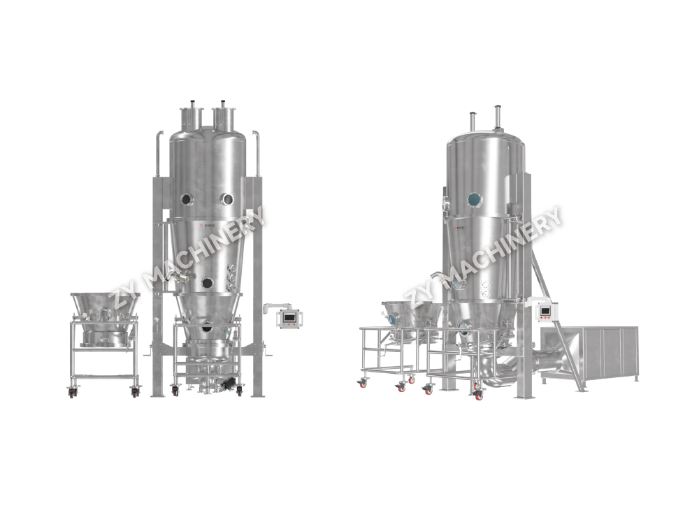 DLP Multi-Functional Fluid-Bed Granulator and Coating MachineCombines granulation, pelletizing, coating and drying in one bowl, reducing transfer steps and supporting compact, grade-controlled production layouts.View Product →
There is no universally correct pattern, only the one that fits your site and your product portfolio. Three arrangements cover most of the projects we work on:
Whichever you choose, draw the future expansion as a dotted line now. A layout that cannot grow gracefully tends to be replaced rather than extended.
Most of these are cheap to fix in a sketch and painful to fix in concrete. That is the whole argument for spending longer on the block plan than feels comfortable.
A layout drawn only for the current batch size will be redrawn within three years. We prefer to start from the laboratory recipe and design the production rooms so that the same process logic, the same transfer points and the same containment approach carry through from bench to commercial scale. That is easier when the lab and production equipment follow one design family; our laboratory equipment range mirrors the production units for exactly this reason, so a formulation developed on a benchtop unit can move to a pilot suite and then to a commercial line without the process being rethought at each stage.
In practice, this means reserving floor space in the production area for one more unit operation than you currently need, and specifying a clear height that allows a taller bowl or a larger bin to be lifted into place later.
A pharmaceutical plant layout design is never finished on the day the drawings are issued. It continues to be tested every time a new product arrives, a batch size grows or a cleaning regime changes. The projects that age well are rarely the most elegant on paper; they are the ones where someone asked, early and stubbornly, where the material goes next, who has to walk there, and how the room will be cleaned afterwards. Get those three answers right and the walls tend to fall into place.
Want to stay up to date?
Contact us via the email address below.
Don't worry about spam. We hate it too!
Mobile Client

Video Account
Phone:+86-15161130178
Tel:+86-519-88674267
Email:czzy188@163.com
Phone:+86-15161132798
Email:zy@zy-drying.com

WeChat ID

Copyright 2026 Changzhou Zhiyang Machinery Equipment Co., Ltd. All Rights Reserved  Oral Solid Dosage Equipment Manufacturer